



Fluting or frosted raceways on a variable-frequency drive (VFD)-driven motor can indicate electrical erosion, but those patterns don’t automatically justify a ceramic upgrade. A hybrid bearing can interrupt current through one bearing while leaving the voltage source, or another current path, unchanged.
Hybrid ceramic bearings for electric motors are worth considering when evidence of failure, electrical path, and mechanical application support the change. Start with evidence from the failed bearing and motor-drive system, not the bearing number alone.
Confirm Electrical Bearing Damage Before Upgrading
A variable frequency drive (VFD) controls motor speed by rapidly switching electrical power. This switching can produce high-frequency common-mode voltage between the motor windings and ground.
Through electrical coupling inside the motor, some of that voltage can reach the shaft. Motor design, cable construction, grounding, bonding, and system capacitance affect the resulting current paths.
Bearing damage occurs when current passes through the contact between the rolling elements and raceways. Under ISO 15243, this damage is classified as electrical erosion. The standard divides electrical erosion into excessive-current erosion and current-leakage erosion.
In VFD-driven motors, current leakage erosion can occur when relatively low-intensity stray current passes through the bearing. The current can produce closely spaced microscopic craters on the rolling surfaces. As the damage progresses, evidence may include:
- Microscopic craters on raceways and rolling elements
- Dull, gray, or frosted running surfaces
- Discolored or degraded lubricant
- Rising bearing noise and vibration
- Fluting that appears as regularly spaced grooves across a raceway

These signs support a diagnosis, but none proves the cause on its own. Evaluate the bearing condition, failure pattern, operating history, grounding and bonding, and the complete motor-drive system before selecting a corrective measure.

Operating history can strengthen the diagnosis. Record whether the problem began after a VFD installation, cable change, grounding modification, motor rebuild, or drive-setting change. EASA’s overview of shaft and bearing currents explains why different current mechanisms may require different corrective actions.
Look for evidence of other failure mechanisms. An offset load zone can indicate misalignment, smearing can result from sliding under insufficient load, and indentations may come from contamination or improper handling. Excess heat can result from overgreasing, insufficient operating clearance, or incorrect lubricant viscosity.
Preserve the evidence before cleaning or discarding a failed bearing. Observations made during removal can be difficult to reconstruct later.
- Photograph the bearing and raceways.
- Mark its drive-end or opposite-drive-end position.
- Record the complete bearing designation.
- Preserve a grease sample when practical.
- Document recent motor, drive, cable, and grounding changes.
Raceway patterns and load zones can help separate electrical damage from mechanical, lubrication, and installation problems. Our bearing-failure analysis guide explains how to document and interpret these patterns.
Understand What Hybrid Construction Changes
A hybrid ceramic bearing combines steel rings with rolling elements made from silicon nitride. Silicon nitride is an engineered ceramic, so the term “ceramic bearing” can be misleading without the hybrid distinction.
Silicon nitride is electrically insulating, which interrupts the conductive path between the steel rings. This can prevent current from discharging through that bearing, provided that no other conductive path bypasses the rolling elements. The material also changes the bearing’s mechanical behavior:
- Lower density reduces rolling-element mass and inertial forces, allowing some hybrid designs to operate with a lower requisite minimum load than comparable all-steel bearings.
- High hardness can improve resistance to certain forms of surface distress.
- High stiffness changes contact behavior under load.
- Rolling-contact properties can support demanding speed or lubricant-film conditions.
- Resistance to particle-induced damage can reduce the progression from some indentations to surface distress.
These characteristics can be useful, but their value depends on the bearing design and operating conditions. Hybrid construction doesn’t correct misalignment, contamination, incorrect fits, inadequate sealing, unsuitable lubrication, excessive load, or excessive load.
A hybrid bearing also doesn’t eliminate the source of shaft voltage. Insulating one bearing can redirect current through another motor bearing, the coupling, or bearings in the driven equipment. The complete electrical path must therefore be evaluated.
Match the Mitigation Method to the Current Path

Hybrid bearings, coated bearings, shaft-grounding devices, and drive-system corrections act at different points in the electrical system. The correct choice depends on how current is generated and where it flows.
- All-steel replacement bearings: Appropriate when evidence points to mechanical damage, contamination, lubrication problems, or incorrect installation rather than harmful bearing current.
- Ceramic-coated bearings: Add an insulating coating to the inner or outer ring. Suitability depends on coating location, insulation impedance, high-frequency capacitance, environment, and current mechanism.
- Hybrid ceramic bearings: Insulate through the rolling elements and may offer mechanical advantages under suitable speed, lubrication, and contact conditions.
- Shaft-grounding devices: Provide a lower-impedance path around a bearing for certain current mechanisms. They require correct placement, reliable shaft contact, and periodic inspection.
- Drive-system corrections: May include symmetrical shielded motor cable, low-impedance high-frequency bonding, improved grounding, common-mode filtering, or suitable output filtering.
A general-purpose reactor or filter shouldn’t be assumed to solve every bearing-current problem. ABB’s technical guide to bearing currents in modern AC drive systems explains how motor size, cable construction, grounding, and current type affect mitigation choices.
Some applications require more than one measure, such as an insulated bearing combined with shaft grounding or drive-system corrections. Our overview of current-insulated bearing options provides background on coated and hybrid designs.
Treat “Drop-In” as a Dimensional Claim
Matching bore diameter, outside diameter, and width can simplify installation. It doesn’t establish that a replacement is mechanically or electrically suitable. Verify these factors before approving a retrofit:
- Complete designation and internal design
- Dynamic and static load ratings
- Reference speed, limiting speed, and actual operating speed
- Requisite minimum load
- Initial and expected operating clearance
- Shaft and housing fits
- Cage, seals, shields, and lubrication
- Radial and axial loading
- Locating or non-locating function
- Orientation, temperature, and contamination exposure
Reference speed is a thermal benchmark, while limiting speed reflects mechanical restrictions associated with the bearing design. Neither value alone establishes an acceptable operating speed under the application’s actual load, lubricant, cage, seal, fit, and temperature conditions.
Internal clearance changes after installation because interference fits and temperature differences can reduce it. Too little clearance can increase friction and heat, while excessive clearance can affect load distribution, noise, and vibration. Very light loads can also allow sliding that contributes to smearing, heat, and cage damage, especially at higher speeds.
Review the electrical arrangement separately. Document the bearings at both motor ends, existing insulation, shaft-grounding devices, motor-frame bonding, cable construction, VFD settings, coupling type, and bearings in the driven equipment.
Shaft-voltage testing may involve energized electrical equipment and exposed rotating parts. It should be performed only by trained personnel using appropriate instruments, guarding, and a task-specific safe-work procedure. During bearing replacement, OSHA’s control-of-hazardous-energy standard applies when unexpected energization, startup, or release of stored energy could cause injury.
Correct removal and installation still matter after selecting the replacement. Our industrial bearing replacement guide covers practices that help prevent mounting damage.
Decide Whether the Upgrade Earns Its Premium
A hybrid ceramic bearing costs more than a conventional all-steel bearing, so the decision should be based on a documented limitation or failure mechanism. A dimensional match and the presence of a VFD aren’t enough. The case becomes stronger when:
- Failure analysis supports electrical discharge through the bearing.
- Failures recur despite verified alignment, lubrication, fits, and installation.
- Speed or lubrication conditions limit bearing performance.
- Motor access makes maintenance or replacement unusually disruptive.
- Failure carries substantial labor, production, or collateral damage costs.
- A suitable hybrid designation meets the mechanical requirements.
- The electrical path has been evaluated before insulation is added.
The case is weaker when the failed bearing wasn’t inspected, mechanical causes remain unresolved, or the proposed replacement matches only the basic bearing number. Compare lifecycle costs rather than purchase prices, using site-specific data rather than an assumed service-life improvement.
Annual current-state cost = Failures per year × parts, labor, downtime, lost production, and collateral damage + routine maintenance
Compare that total with the bearing premium, installation expense, additional electrical mitigation, and expected maintenance changes. For a group of similar critical motors, a controlled pilot can provide stronger evidence than an immediate fleet-wide conversion. Before requesting a recommendation, gather the information needed to evaluate the bearing and surrounding system:
- Motor make, model, frame, power, speed range, and duty
- Bearing designations at both motor ends
- Driven equipment, coupling type, and known loads
- VFD model, cable length, and carrier-frequency setting
- Grounding, bonding, and shaft-grounding configuration
- Failure photographs, condition trends, and operating hours
- Grease, relubrication interval, sealing, and fit information
- Failure frequency and site-specific downtime cost
This record lets you check the proposed solution against observed failures, mechanical requirements, and the complete motor-drive system. It also gives a bearing specialist more to work with than a part number.
Where SKF CeraDrive Fits
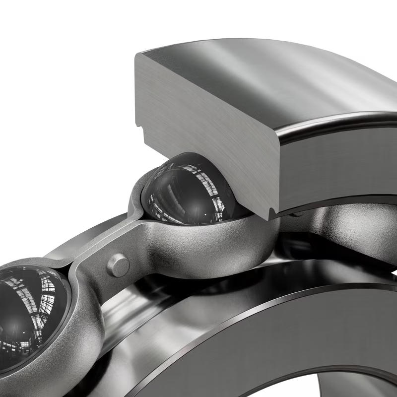
SKF CeraDrive is a series of hybrid ceramic deep-groove ball bearings developed for electric-motor applications. The design combines high-performance steel rings with smaller silicon nitride rolling elements and retains the external dimensions of the corresponding standard-size bearings. Those dimensions can simplify integration, but they don’t eliminate the application checks above.
The SKF CeraDrive brochure currently includes six 63-series designations with additional sizes planned. The brochure illustrates CeraDrive’s advantages over comparable all-steel bearings, including lower minimum-load requirements, higher limiting speeds, and longer grease life.
Current CeraDrive range as of September, 2026:
| CeraDrive Designation | ID Bore × OD × Width | Basic Dynamic Load Rating | Performance |
| 6315/HC5C3VA505 | 75 × 160 × 37 mm | 99.5 kN | 6,700 r/min |
| 6316/HC5C3VA505 | 80 × 170 × 39 mm | 114 kN | 6,300 r/min |
| 6317/HC5C3VA505 | 85 × 180 × 41 mm | 130 kN | 6,000 r/min |
| 6318/HC5C3VA505 | 90 × 190 × 43 mm | 146 kN | 5,600 r/min |
| 6319/HC5C3VA505 | 95 × 200 × 45 mm | 159 kN | 5,300 r/min |
| 6322/HC5C3VA505 | 110 × 240 × 50 mm | 186 kN | 4,300 r/min |
In SKF bearing designations, HC5 denotes silicon-nitride rolling elements, and C3 denotes radial internal clearance greater than Normal. C3 clearance isn’t automatically correct because the external dimensions match an existing bearing. Fits, temperature differences, speed, and required operating clearance still control the selection.
Use the current SKF CeraDrive technical overview to check available sizes and technical data. Final selection still requires the complete designation and application conditions.
Bring Us the Failure Evidence Before Selecting a Replacement
Preserve the failed bearing, and document the motor, drive, grounding, load, lubrication, and operating history before ordering a replacement. Those details help determine whether a hybrid ceramic bearing addresses the failure mechanism or merely changes one part of the system.
Our bearing and motor specialists can review the evidence, verify the application requirements, and help evaluate the SKF products and technical resources available through our team. Bring us the complete bearing designations from both motor ends, along with failure photographs and motor-drive information, so we can start with the application rather than the part number.
Request a Quote on Insulated Bearings for Electric Motors
Or

Shop Hybrid Motor Bearings Online
Check out ShopIBT.com to find the bearing and power transmission products for your needs!
