




A replacement rod end can have the correct bore, thread, and overall dimensions and still be wrong for the application.
Effective rod end selection requires matching seven factors: load magnitude, load direction, movement, misalignment, required precision, operating environment, and maintenance needs. Overlooking one can lead to excessive play, binding, corrosion, liner damage, or structural failure.
A rod end combines a spherical bearing interface with an eye-shaped housing and a threaded or weldable shank. See our introductory guide for a basic explanation of what industrial rod ends are and how they work. In this article, we’ll focus on selecting the right rod end for your application.
Rod End Selection Starts with the Load
Load magnitude matters, but so do its direction and behavior. A rod end that supports a stationary load may not provide acceptable life when that load moves, reverses, or strikes the joint repeatedly.
Identify the Load Direction
Rod ends are primarily intended to support radial loads acting along the shank centerline. An angled or off-axis force creates additional bending stress in the shank and threaded connection.
Axial force applied to the face of the bearing presents another limitation. Axial capacity may depend on how the bearing is retained within the rod-end eye, not just the strength of the ball or race.
Evaluate the complete load path, including the rod end, pin, clevis or mounting bracket, spacers, threads, locking hardware, and supporting structure. A clevis is a U-shaped bracket that supports the rod-end eye on both sides.
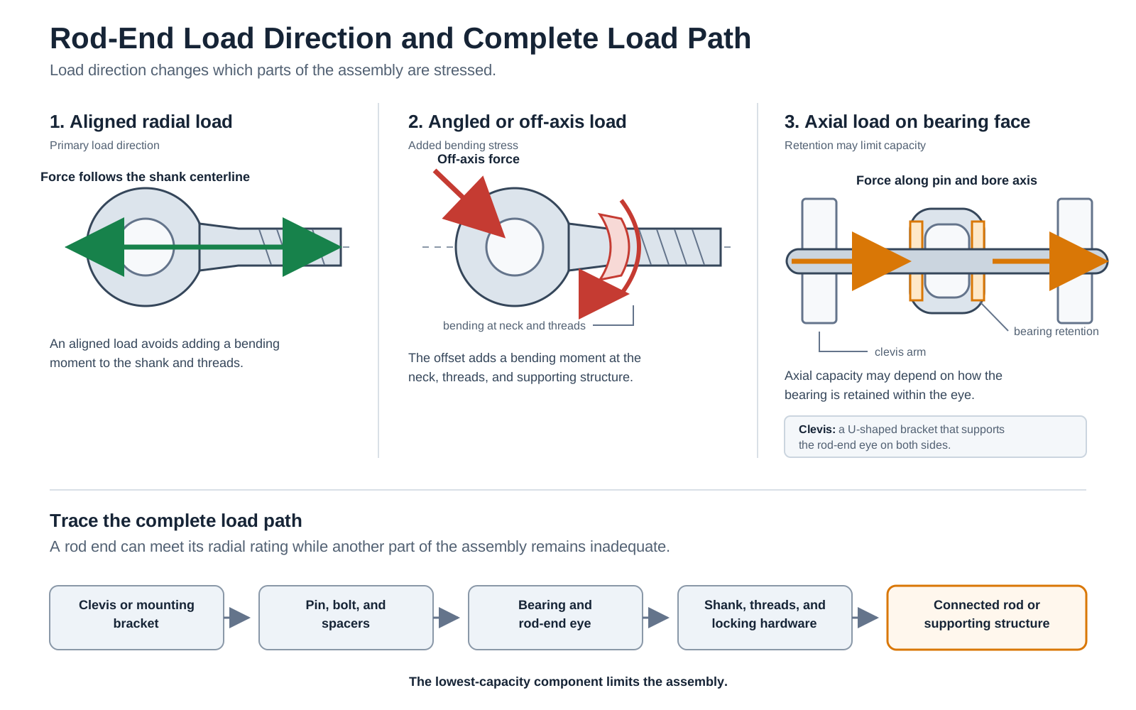
A rod end with adequate radial capacity can still be part of an inadequate assembly if the pin bends, the clevis spreads, the threads aren’t engaged far enough, or the shank is repeatedly side-loaded.
If the load direction isn’t obvious, mark the expected forces on a photo or sketch. Check several positions in the machine cycle because the direction may change as the linkage moves.
RBC’s Heim rod-end engineering data illustrates why this matters. Its static radial capacity calculations consider race-material compressive strength, rod-end head strength, and shank strength. The lowest value can limit the rod end.
Separate Static, Dynamic, Reversing, and Shock Loads
Identify the conditions the rod end must handle:
- Static load: The rod end is loaded without relative movement at the bearing interface.
- Dynamic load: The bearing surfaces move while carrying the load.
- Pulsating load: Load magnitude changes without a complete reversal in direction.
- Reversing load: The direction of force changes during operation.
- Shock load: A jam, impact, hard stop, or sudden reversal produces a brief load spike.
A cylinder holding a fixture in position presents a different challenge than a packaging linkage cycling continuously. A machine that normally runs smoothly may also experience much higher loads during startup, a jam, or an emergency stop.
Document the normal load, peak load, and abnormal conditions the linkage is expected to survive. These conditions often explain why a rod end that appears adequate based on average load is wearing prematurely.
Understand What the Ratings Mean
Rod-end catalogs may publish several types of load ratings:
- Static radial load: A stationary load applied radially under the manufacturer’s stated conditions
- Dynamic load rating: A manufacturer-specific value used when movement occurs under load
- Fatigue load: A load associated with a defined cyclic test
- Ultimate static load: A test threshold associated with fracture under stated conditions
- Axial proof load: A test of bearing retention within the rod-end eye
These values aren’t interchangeable. An ultimate or proof load should not be treated as a recommended operating load.
RBC’s M81935/1 male rod-end data and M81935/2 female rod-end data demonstrate why the definitions matter. The sheets list ultimate static, fatigue, and axial proof loads under specified test conditions.
Before comparing two rod ends, check:
- How each rating is defined
- The direction of the test load
- Whether movement occurred under load
- The number and type of cycles
- The test temperature
- Whether the value is a working, proof, fatigue, or ultimate load
The required design margin depends on shock, cycling, uncertainty in the actual load, and the consequences of failure. Safety-critical and high-consequence linkages require formal engineering review rather than a dimensional cross-reference alone.
Define the Movement and Installed Geometry

The rod end must fit the machine and move through its complete operating cycle without binding or contacting adjacent components.
Document the Motion Cycle
Record the angle of movement, cycles per hour or shift, direction reversals, movement speed, time spent stationary under load, and required service life.
Spherical plain rod ends are commonly used for oscillating, tilting, and articulating movements at relatively low speeds. They shouldn’t automatically be treated as rolling bearings intended for continuous high-speed rotation.
A slowly adjusted linkage and a packaging mechanism that cycles thousands of times per shift impose different demands on the bearing surface, even if their peak loads are similar. A short operating video can reveal reversals, vibration, and interference that aren’t apparent when the machine is stopped.
Check the Available Misalignment
The misalignment angle shown in a catalog may not equal the usable angle after installation.
A clevis, bolt head, washer, or spacer can restrict movement before the rod end reaches its catalog limit. Deflection under load may further reduce the available clearance.
Inspect the linkage through its full cycle and check:
- Normal and maximum operating angles
- Deflection under peak load
- Clearance between the housing and clevis
- Clearance around bolts, washers, and spacers
- Movement during jams or hard stops
Once the housing or adjacent hardware makes contact, the joint has exhausted its available articulation. Further movement can produce binding or redirect force into the shank and mounting hardware.
ISO 12240-4 defines dimensions, tolerances, radial internal clearances, and tilt angles for several spherical plain rod-end series. It does not cover every design, such as airframe rod ends and certain rod ends intended for direct connection to hydraulic cylinders.
Determine How Much Play Is Acceptable
Internal clearance affects how far a linkage can move before it responds. A small amount of play may be acceptable in a manually adjusted mechanism but cause inconsistent travel in an automation or positioning system.
Consider the maximum acceptable radial play, backlash at the end of the linkage, required positioning repeatability, breakaway torque, and actuator force available to start movement.
A tighter rod end may improve positioning but may also require more force to move. “Precision” should be tied to a measurable requirement for clearance, torque, or positioning.
Match the Construction to the Application
Rod-end construction affects strength, clearance, friction, material selection, and maintenance.
Four-Piece Rod Ends

A four-piece rod end uses separate race inserts, typically made from brass or aluminum bronze, between the ball and housing.
RBC Heim’s four-piece designs feature reduced internal clearance and smooth operation. Depending on the series, they may suit dynamic linkages where consistent movement and minimal play are important.
Metal-to-metal four-piece designs still require lubrication. Their capacity depends on the body, inserts, ball, shank, and exact series.
Two-Piece Rod Ends

In a two-piece rod end, the body is formed around the spherical ball. Certain series have a relatively heavy body cross-section designed to withstand high static, reversing, or shock loads.
Traditional metal-to-metal designs require lubrication. Insufficient lubrication can increase friction, wear, and galling.
In lined two-piece rod ends, a liner separates the ball from the bearing surface. Selection must account for the liner’s load, movement, temperature, speed, and chemical compatibility limits.
Cartridge and Ball-Bearing Rod Ends
A cartridge design places a separate spherical bearing assembly inside the rod-end housing. This allows the ball, race, liner, and housing materials to be selected for specific performance or specification requirements. Axial loading and cartridge retention still have to be evaluated.
Ball-bearing rod ends use rolling elements instead of a spherical sliding interface. They may be appropriate where low friction and smooth movement are priorities, but their load, speed, sealing, contamination, and misalignment limits must be checked.

The Heim industrial rod-end overview PDF compares several two-piece, four-piece, lined, thermoplastic-race, and ball-bearing designs.
Match Lubrication and Materials to the Environment
The bearing interface must withstand the application’s maintenance practices, contamination, chemicals, and temperature extremes.
Metal-to-Metal vs. Self-Lubricating Rod Ends
Metal-to-metal rod ends require regular lubrication. Depending on the design, lubricant may be supplied through a grease fitting or by applying oil..
Before selecting a lubricated rod end, confirm that technicians can safely reach the lubrication point, apply the correct lubricant at a practical interval, and keep exposed grease from collecting abrasive contamination.
PTFE-lined and engineered-polymer rod ends suit applications where relubrication is difficult or undesirable. Their dry bearing interfaces can also reduce debris buildup around exposed grease.
These designs are not suitable for every application. Liner performance depends on load, movement, temperature, speed, and chemical exposure. Do not add lubricant to a self-lubricating rod end unless the liner is designed to accept it.
Maintenance-free means the bearing interface does not require scheduled relubrication. It does not mean the rod end never needs inspection.
Account for Water, Chemicals, and Washdown

Document exposure to water, humidity, salt, cleaning chemicals, acids, caustics, abrasive particles, washdown, and temperature extremes.
Consider the entire material system, including the housing, ball, race, liner, adhesive, seals, and coating. Stainless steel provides improved corrosion resistance in many environments, but it is not immune to all chemicals or corrosion mechanisms.
Use in food-processing equipment also does not automatically establish compliance with FDA, NSF, USDA, 3-A, or direct food contact. Confirm any required certification for the exact product and application.
Use Wear Patterns as Selection Clues
Clean and inspect the old rod end before disposal. Its condition may reveal requirements that aren’t shown on the equipment drawing.
- Increasing play: Check load, cycles, liner condition, contamination, and original clearance.
- Binding or high friction: Look for corrosion, debris, chemical attack, liner damage, or clevis interference.
- Bent or cracked shank: Investigate side loading, shock, inadequate size, support, and thread engagement.
- Movement of a cartridge within the eye: Check for axial loading, overload, or retention damage.
- Uneven wear: Look for restricted articulation, edge loading, incorrect spacers, or linkage distortion.
- Contaminated grease: Review sealing, contamination control, and relubrication practices.
- Damaged threads or loose hardware: Check engagement, locking method, vibration, and installation.
These observations suggest questions to investigate. They don’t prove a single root cause.
Record the full part number, photograph the component, and capture the surrounding linkage before removal.
Where RBC’s Heim Rod Ends Fit

RBC Bearings offers Heim rod ends in multiple constructions, including:
- Four-piece designs for controlled clearance and smooth movement
- Two-piece designs for certain static, reversing, and shock-loaded applications
- PTFE-lined and thermoplastic-race designs where relubrication is difficult
- Ball-bearing rod ends for low-friction movement
- Stainless designs for corrosive and washdown environments
- AS81935 rod ends for specification-controlled aerospace applications
New PTFE-Lined Stainless Heim Rod Ends
RBC offers lined stainless steel rod ends in two series: MxCRTSS/FxCRTSS and HMTxSS/HFTxSS.
HMTxSS and HFTxSS rod ends combine heat-treated stainless steel components with a PTFE liner. Their design provides tight ball-to-race clearances, self-lubricating operation, corrosion resistance, and high radial-load capability.
MxCRTSS and FxCRTSS rod ends use a two-piece design with a 17-4PH corrosion-resistant steel body, a 440C corrosion-resistant steel ball, and a PTFE liner. The liner separates the bearing surfaces, eliminating metal-to-metal contact and the need for scheduled grease reapplication at that interface.
These lined stainless designs may suit food-processing, packaging, medical, marine, washdown, paper-processing, and robotic equipment. Those examples do not establish certification or suitability for a specific application.
Final selection should account for load, movement, temperature, chemical compatibility, required clearance, and applicable regulatory requirements.
Gather This Information Before Requesting a Rod End
Provide more than the old part number.
Component and dimensions
- Manufacturer and full part number
- Male, female, or weldable shank
- Right-hand or left-hand thread
- Bore and pin diameter
- Thread diameter, pitch, and engagement length
- Housing width, center height, and available space
- Current liner, seals, and lubrication fitting
- Service history and reason for replacement
Application conditions
- Normal and peak loads
- Load direction
- Static, oscillating, reversing, or shock-loaded service
- Angle and frequency of movement
- Required misalignment
- Acceptable play or positioning error
- Operating temperature
- Water, dust, chemicals, or washdown exposure
- Lubrication access and current lubricant
- Consequences of failure
Include photos of the rod end and complete linkage, a short operating video, and details about recent jams, overloads, or machine changes. These can reveal side loading, interference, poor thread engagement, and contamination that a part number cannot show.
If the rod end is attached to a cylinder, document the cylinder and mounting arrangement.
IBT Industrial Solutions can help review this information and narrow the appropriate Heim rod end options. Contact your local IBT representative with the part number, dimensions, operating conditions, and photos of the linkage.
Shop RBC Rod Ends Online
Check out ShopIBT.com to find the bearing and power transmission products for your needs!
